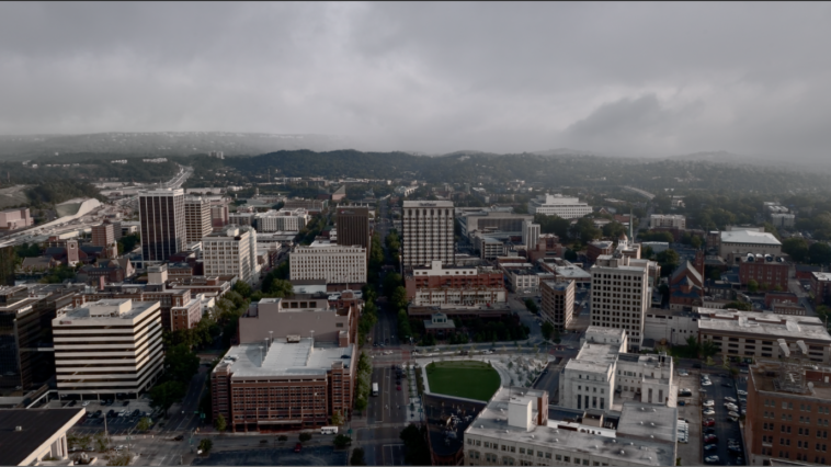
In this post, I will share my studies on HDRI coverage maps in Nuke. What led me to research this topic was an idea for a personal project: replacing the sky in a video and changing the entire atmosphere to make it a cloudy day.
Initially, this seemed like a simple task, but dealing with camera issues and HDRI projected on a sphere, I came across the following video that served as my main guide:
Seeing the HDRI map generated by the node setup developed by the author of the video, I decided that I would delve deeper and learn everything this content had to offer, even though the level of experience needed to fully understand this video was above my level at that time.
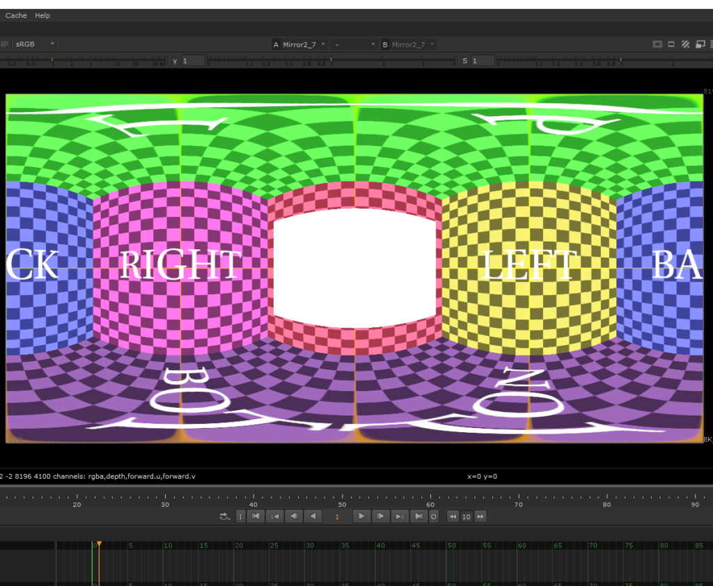
As an aspiring Mid-level Nuke Compositor who still has a lot to learn, I needed the help of the Nuke Copilot made with Chat GPT. It has a solid database managed by professionals in the field. It was developed as a knowledge base and therefore does not invent random information to give you an answer. It searches the database, and if it doesn’t find anything, it guides you on where you can look to find reliable information yourself.
The response it gave me was this:

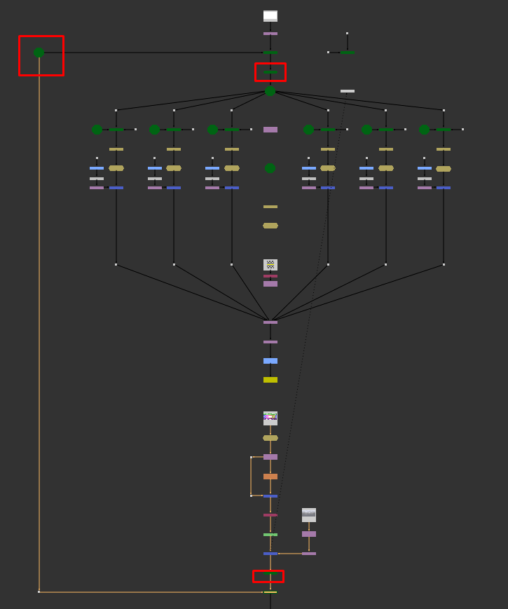
Basically, the applications of the Coverage Map generation process are more for shot sequences where the cameras constantly change positions. This way, it is necessary to know the position where the HDRI was in the previous shots to avoid accidentally breaking the realism of the scenes. I highly recommend watching the video from the Comp Lair channel that I linked above. I reproduced the entire setup from the video for the shot in question.
I reproduced the entire setup I learned from the video for the shot where I needed to replace the sky, and for this, I needed to do a good camera tracker of the scene.

Right after the camera tracking, I projected a Constant node onto a sphere with the same limits as the tracked camera lens. Here, it is important that the sphere where the Constant is projected is at the correct scale. For this, it might be useful to use a PointClouds node.
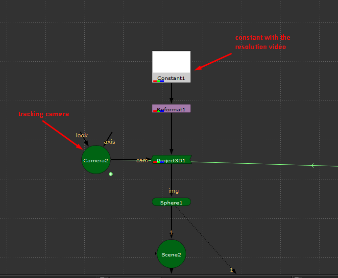
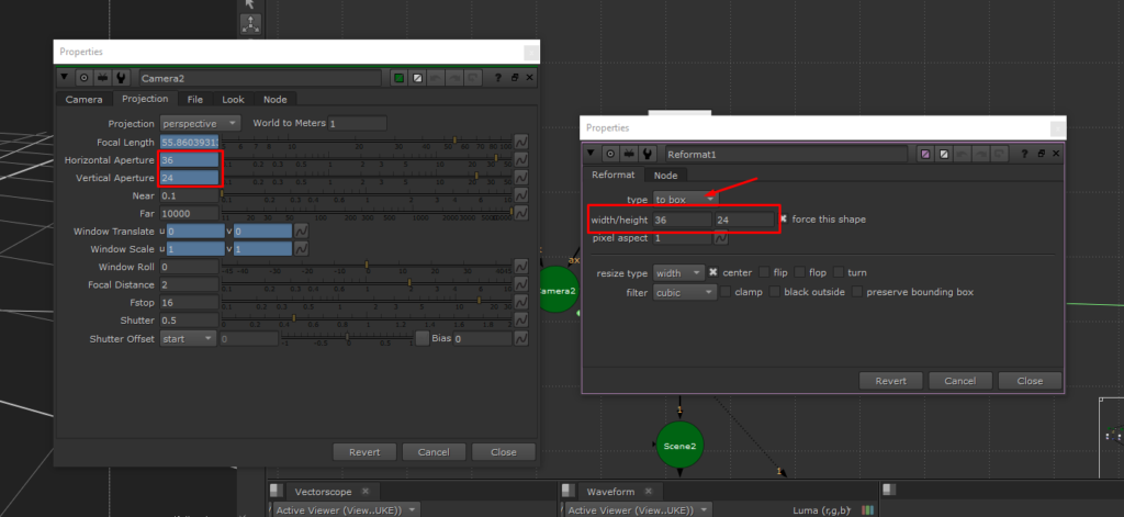
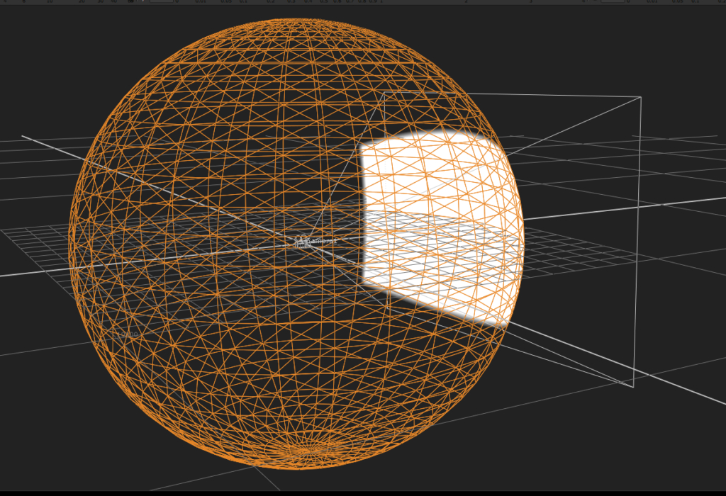
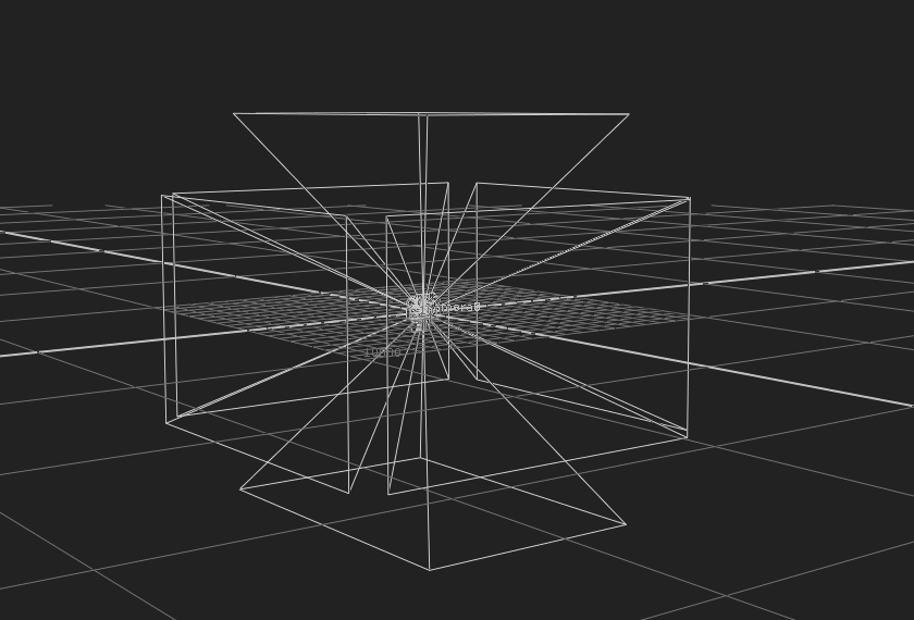
Now, by positioning 6 cameras with the same projection settings as the tracked camera at different angles, all with a ScanlineRender with the BG input connected to a Reformat node configured to square256.
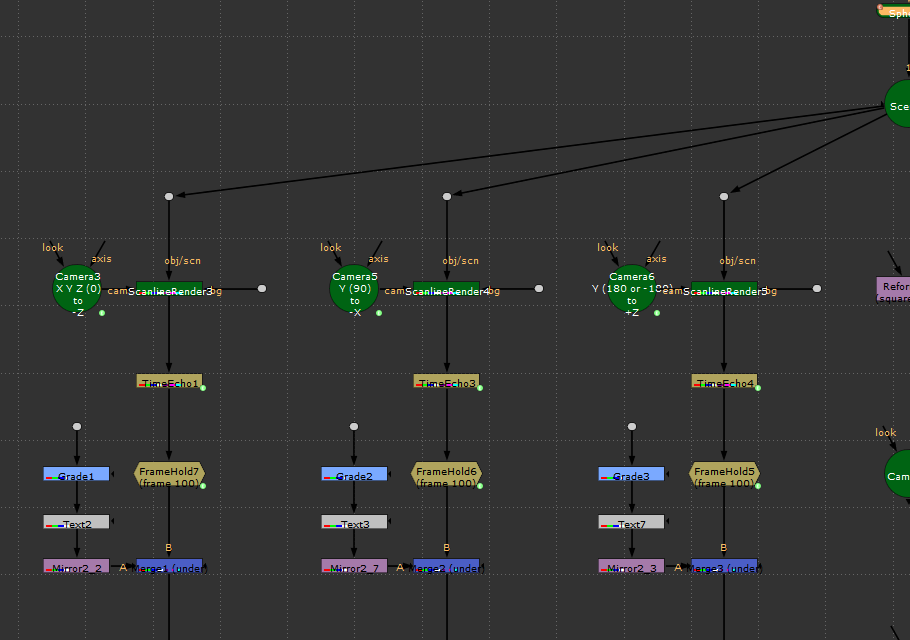
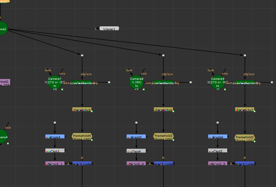

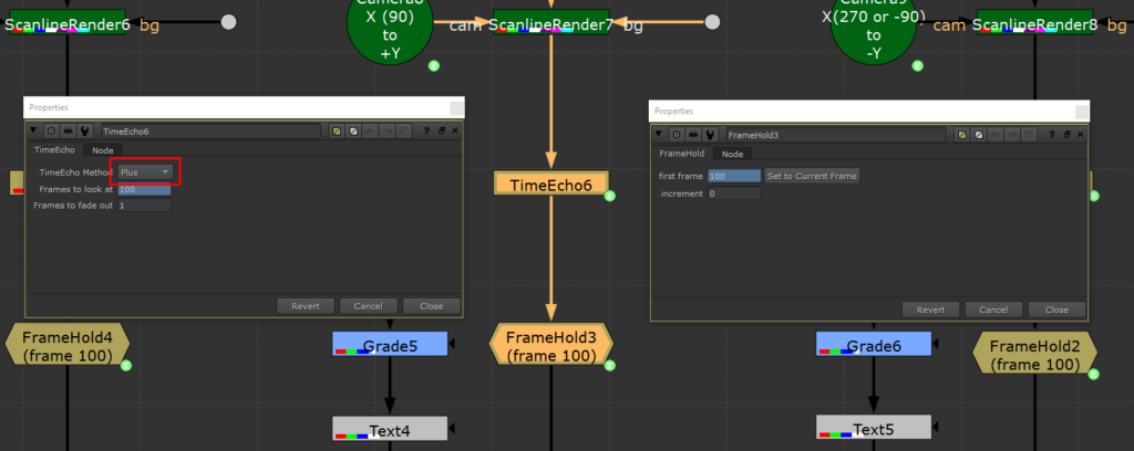
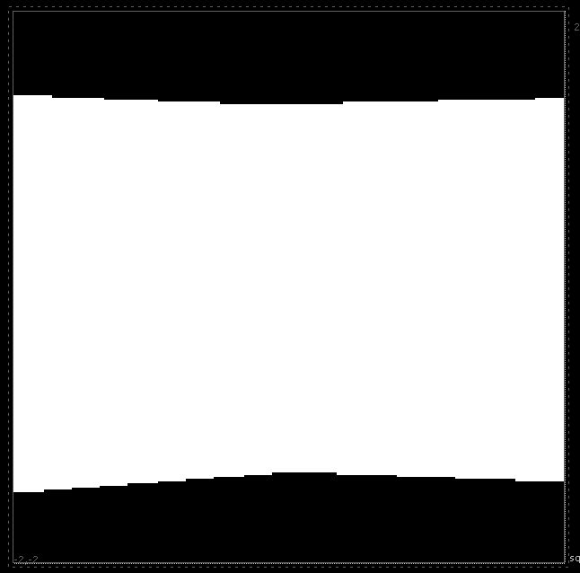
Below the ScanlineRender, we will position a TimeEcho node and a FrameHold, both configured to the last frame of the shot. The TimeEcho needs to be set to Plus. Here, we should already be able to see a white shape in the alpha channel in one of the ScanlineRenders.
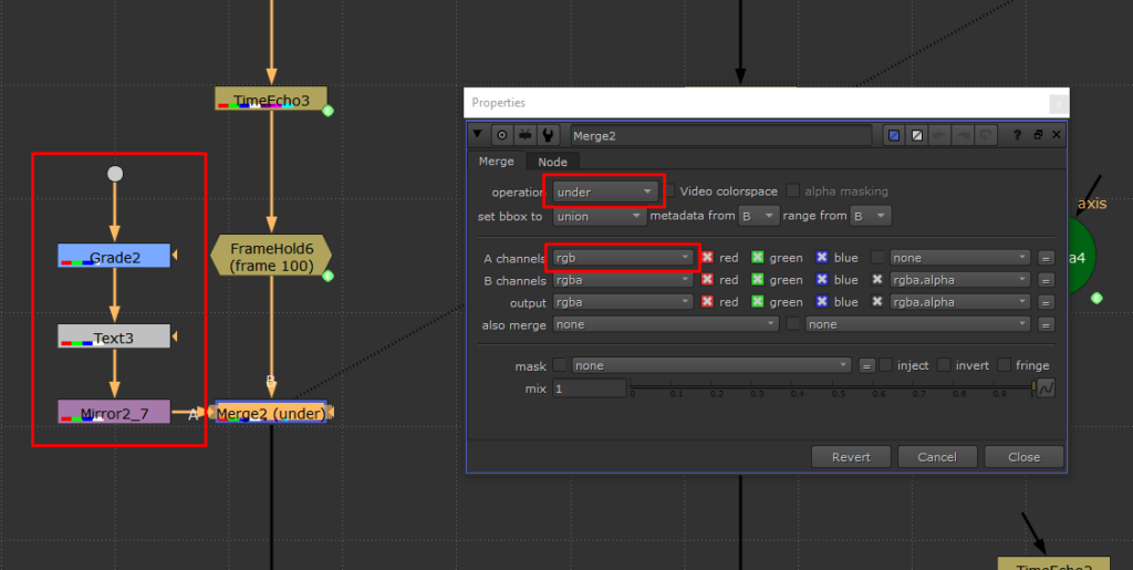
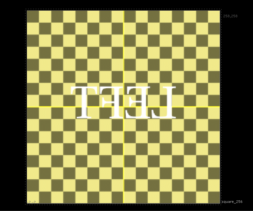
Below each FrameHold, we will merge a CheckerBoard with a Reformat set to square256, which will serve as a guide. The merge needs to be set to Under and with the A input in RGB only.
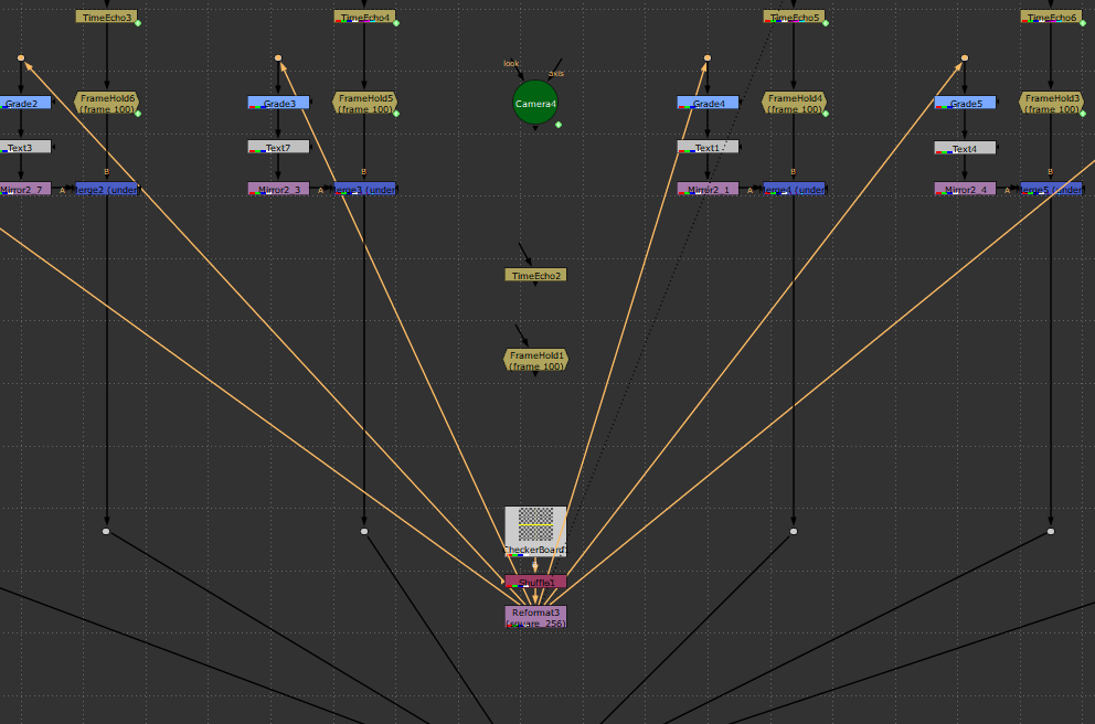
Now we just need to connect everything to a SphericalTransform node, with the output configured to the same resolution as the HDRI map that will be used, on each respective axis.
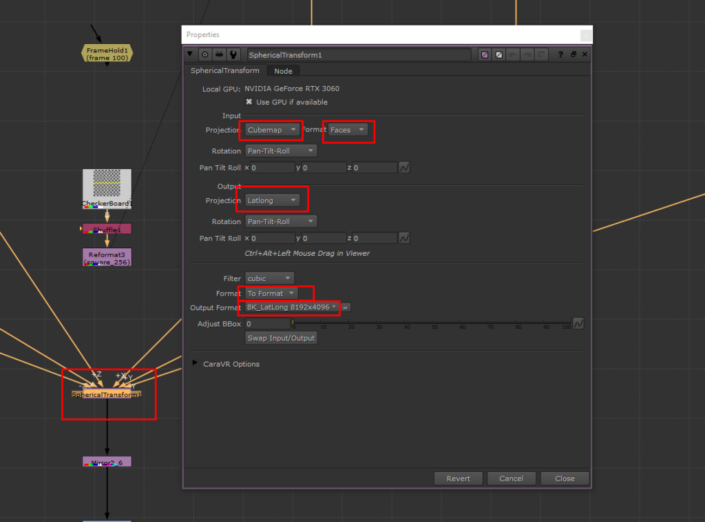
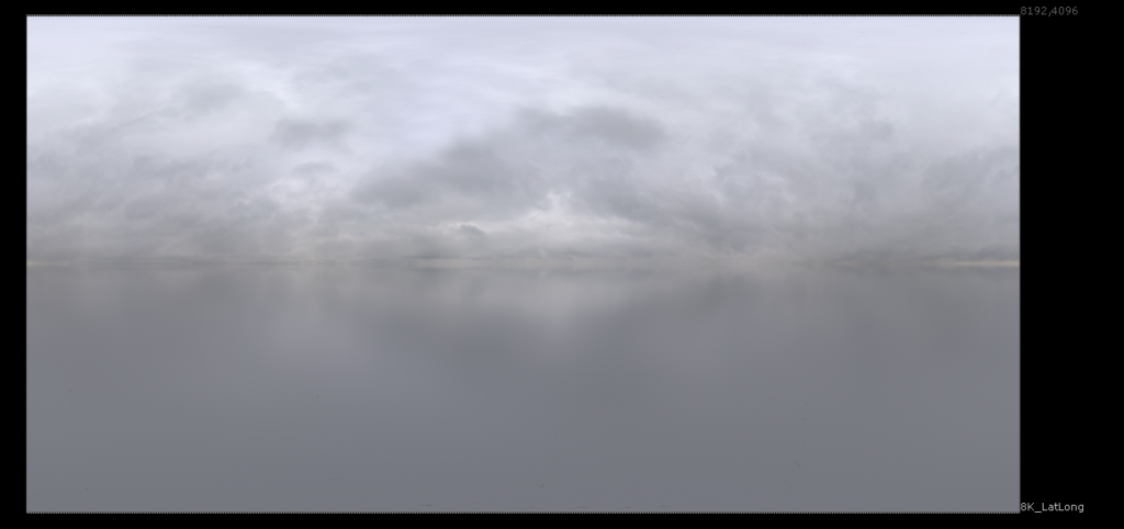
The result will be an alpha map of the HDRI, marked exactly in the direction the tracked camera is pointing. That’s why it was important to use the sphere at the same size that will be used in the shot.
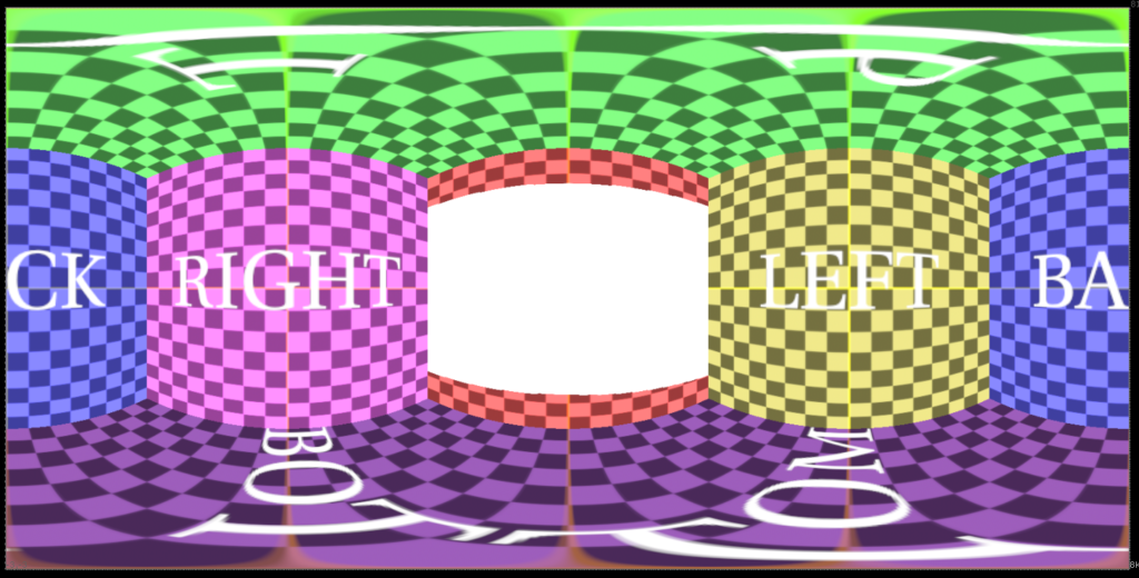
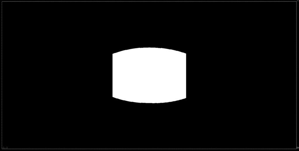
With this in hand, now we can know exactly where the camera was pointed and even make markings on the HDRI.
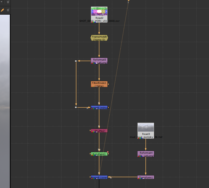
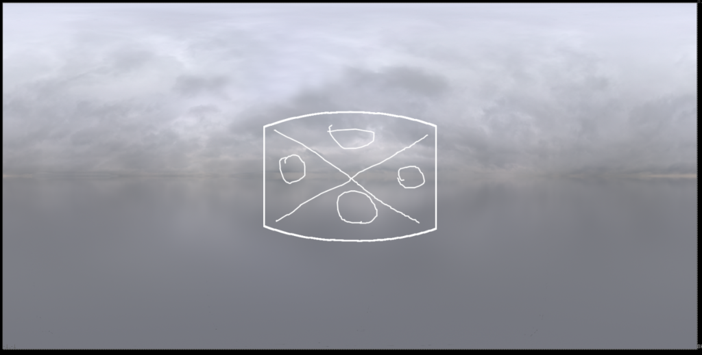
Using the same sphere and camera from the beginning of the setup, we will project the HDRI and verify if the markers are indeed correct.
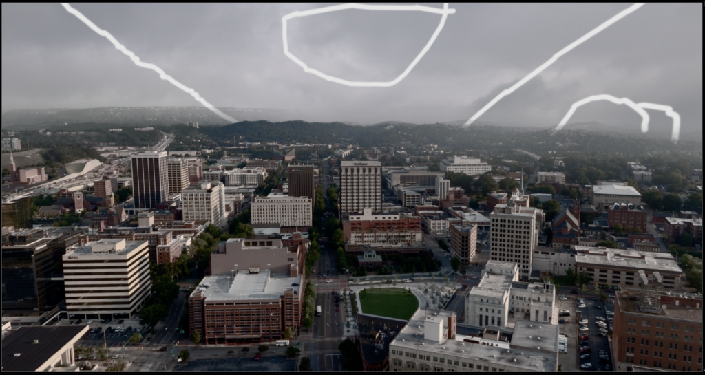
As we can see, the markers align perfectly, and the Coverage Map is now ready and functional. This process helped me to paint and refine subtle details in the HDRI I used, and its applications are broad, such as in Matte Painting.
Despite spending many hours to truly understand everything that wasn’t detailed in the original video, I finally managed to complete the entire process and grasp each step thoroughly. This has given me a great familiarity with the subject as well as a deeper understanding of some nodes that were new to me.
I hope this post, along with the tutorial video, helps you replicate this study on your own! Thank you for reading this far.
